


| Model | HDM3055H | HDM3055B | HDM3055A | HDM3055S | HDM3055 |
| Resolution bit | 5 1/2 | 5 1/2 | 5 1/2 | 5 1/2 | 5 1/2 |
| DCV basic precision | 150 ppm | 150 ppm | 150 ppm | 150 ppm | 150 ppm |
| Maximum reading rate | 30,000 rdgs/s | 30,000 rdgs/s | 30,000 rdgs/s | 30,000 rdgs/s | 30,000 rdgs/s |
| Memory | 10,000 readings | 10,000 readings | 10,000 readings | 10,000 readings | 10,000 readings |
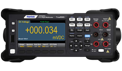
| Double-display measurement function | √ | √ | √ | √ | √ |
| Statistical graph |
Histogram,
bar graph, trend graph |
Histogram,
bar graph, trend graph |
Histogram,
bar graph, trend graph |
Histogram,
bar graph, trend graph |
Histogram,
bar graph, trend graph |
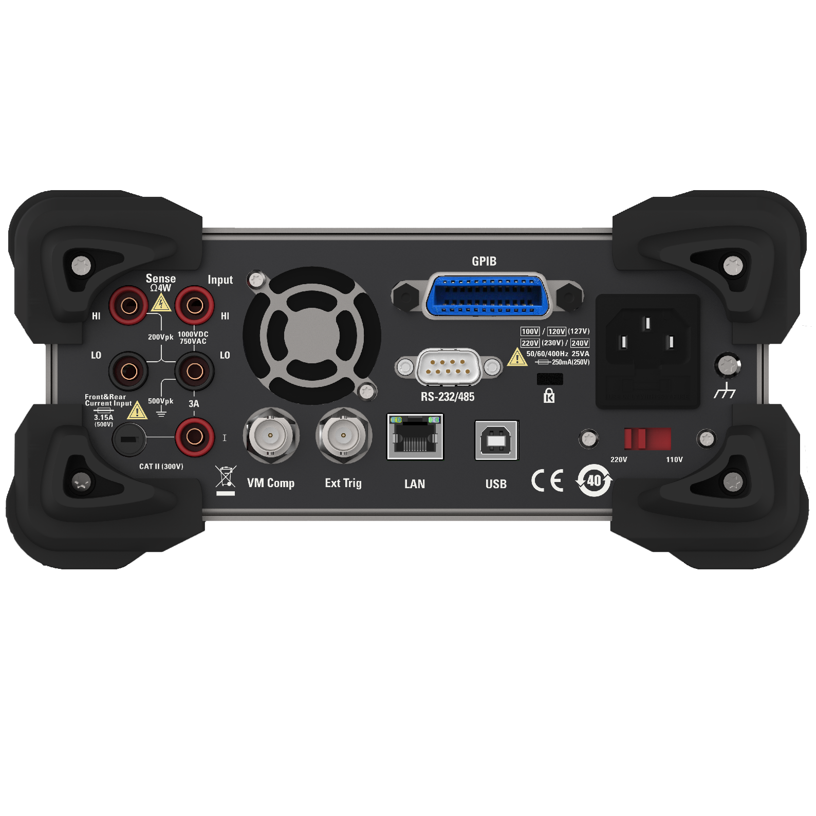
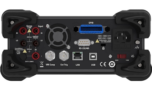
| Interface | USB、RS232/485、LAN、GPIB | USB、RS232/485、LAN | USB、RS232/485 | USB、RS232/485 | USB、RS232/485 |
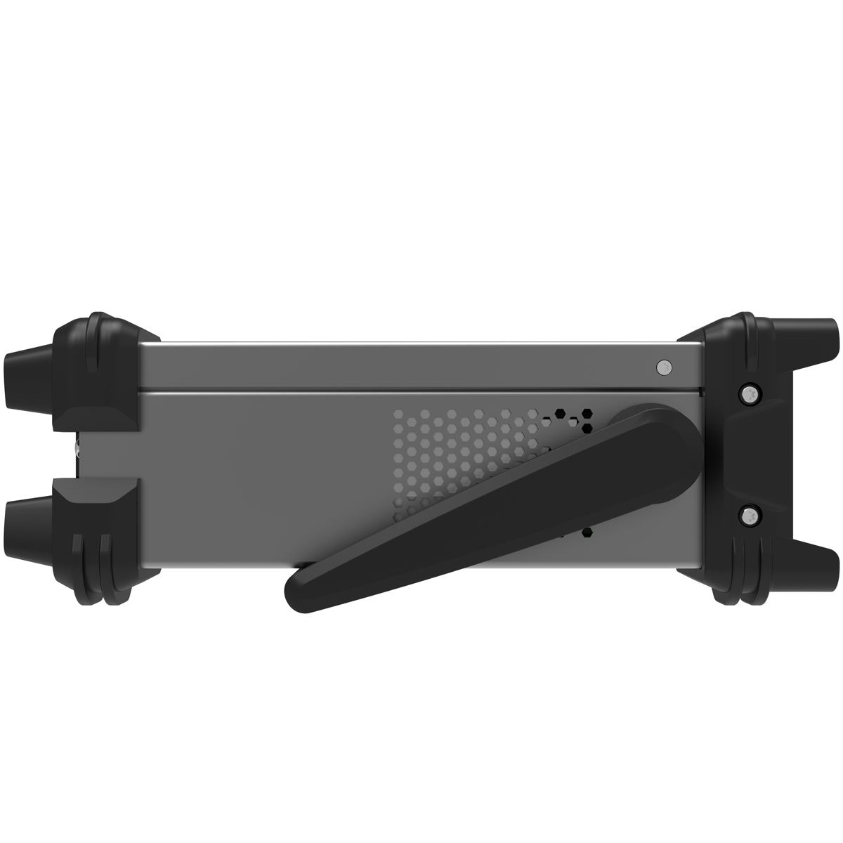
| Input terminal |
Front-panel Rear-panel |
Front-panel Rear-panel |
Front-panel Rear-panel |
Rear-panel | Front-panel |
| DC precision technical index: ± (% reading + % range) | ||||
| Range1/Frequency | Test current or Load voltage | Input impedance | 1 year | Temperature coefficient/°C |
| 23℃± 5 °C | 0 ℃-18 ℃ | |||
| DC voltage | 28 ℃-55 ℃ | |||
| 100 mV | — | 10 MΩ or>10 GΩ | 0.018 + 0.008 | 0.0020 + 0.0008 |
| 1 V | — | 10 MΩor>10 GΩ | 0.015 + 0.005 | 0.0015 + 0.0008 |
| 10 V | — | 10 MΩ | 0.015 +0.005 | 0.0020 + 0.0008 |
| 100 V | — | 10 MΩ | 0.015 + 0.005 | 0.0020 + 0.0008 |
| 1000 V | — | 10 MΩ | 0.015 + 0.005 | 0.0020 + 0.0008 |
| resistance2 | ||||
| 100 Ω | 1 mA | — | 0.050 + 0.008 | 0.0060 + 0.0008 |
| 1k Ω | 1 mA | — | 0.050 + 0.008 | 0.0060 + 0.0005 |
| 10 kΩ | 100 μA | — | 0.050 + 0.005 | 0.0060 + 0.0005 |
| 100 kΩ | 10 μA | — | 0.050 + 0.005 | 0.0060 + 0.0005 |
| 1 MΩ | 5 μA | — | 0.060 + 0.005 | 0.0060 + 0.0005 |
| 10 MΩ | 500 nA | — | 0.250 + 0.005 | 0.0250 + 0.0005 |
| 100 MΩ | 500 nA || 10 MΩ | — | 2.000 + 0.005 | 0.3000 + 0.0005 |
| DC | ||||
| 100 μA | <0.02 V | — | 0.050 + 0.015 | 0.007 + 0.0015 |
| 1 mA | <0.2 V | — | 0.050 + 0.007 | 0.007 + 0.0010 |
| 10 mA | <0.02 V | — | 0.050 + 0.015 | 0.008 + 0.0015 |
| 100 mA | <0.2 V | — | 0.050 + 0.007 | 0.008 + 0.0010 |
| 1 A | <0.1 V | — | 0.100 + 0.015 | 0.012 + 0.0015 |
| 3 A | <0.3 V | — | 0.250 + 0.007 | 0.015 + 0.0010 |
| 10 A | <0.02 V | — | 0.250 + 0.007 | 0.015 + 0.0010 |
| Breakover3 | ||||
| 1 kΩ | 1 mA | — | 0.100 + 0.100 | 0.005 + 0.005 |
| Diode test4 | ||||
| 5 V | 1 mA | — | 0.05 + 0.03 | 0.005 + 0.005 |
| ACprecision technical index: ± (% reading + % range) | ||||
| True RMS AC voltage 5,6 | Test current or Load voltage | Input impedance | 1 year | Temperature coefficient/°C |
| 23 ℃± 5 °C | 0 ℃-18 ℃ | |||
| 28 ℃-55 ℃ | ||||
| 100 mV Range | ||||
| 20 Hz-45 Hz | — | — | 1.00 + 0.10 | 0.02 + 0.02 |
| 45 Hz-10 kHz | — | — | 0.20 + 0.10 | 0.02 + 0.02 |
| 10 kHz-30 kHz | — | — | 1.50 + 0.30 | 0.05 + 0.02 |
| 30 kHz-100 kHz7 | — | — | 3.00 + 0.30 | 0.10 + 0.02 |
| Range: 1 V, 10 V, 100 V and 750 V | ||||
| 20 Hz-45 Hz | — | — | 1.00+0.108 | 0.02+0.02 |
| 45 kHz-10 kHz | — | — | 0.20+0.10 | 0.02+0.02 |
| 10 kHz-30 kHz | — | — | 1.50+0.30 | 0.05+0.02 |
| 30 kHz-100 kHz3 | — | — | 3.00+0.309 | 0.10+0.02 |
| True RMS AC current2 | ||||
| Range: 100 uA-10 A | ||||
| 20Hz-45 Hz | — | — | 1.50 + 0.10 | 0.02+0.02 |
| 45Hz-1 kHz | — | — | 0.50 + 0.10 | 0.02+0.02 |
| 1 kHz-10 kHz10 | — | — | 2.00 + 0.20 | 0.02+0.02 |
| Frequency: technical index ±(% reading+3 counts) | ||||
| Frequency range11 : 100 mV,1 V,10 V,100 V and 750 V | ||||
| 20 Hz – 300 kHz12 | — | — | 0.02+3 | 0.005 |
| Frequency resolution | Frequency | Resolution | ||
| Range13: 100 mV,1 V,10 V,100 V and 750 V | 119.999 Hz | 0.001 Hz | ||
| 1.19999 kHz | 0.00001 kHz | |||
| 11.9999 kHz | 0.0001 kHz | |||
| 119.999 kHz | 0.001 kHz | |||
| 300.000 KHz | 0.001 KHz | |||
| Capacitance1 | Test current or probe type | Input impedance | 1 year | Temperature coefficient/°C |
| 23 ℃± 5 °C | 0 ℃-18 ℃ | |||
| 28 ℃-55 ℃ | ||||
| 1.000 nF | 5 μA | — | 1. + 0.5 | 0.02 + 0.001 |
| 10.00 nF | 5 μA | — | 1 + 0.5 | 0.02 + 0.001 |
| 100.0 nF | 10 μA | — | 1 + 0.5 | 0.02 + 0.001 |
| 1.000 μF | 100 μA | — | 1 + 0.5 | 0.02 + 0.001 |
| 10.000 μF | 1 mA | — | 1 + 0.5 | 0.02 + 0.001 |
| 100.00 μF | 1 mA | — | 1 + 0.5 |
0.02 + 0.001 |
.jpg)

.jpg)
.jpg)
.jpg)
.jpg)
.jpg)
.jpg)
.jpg)
.jpg)
.jpg)
.jpg)
20241202140134.jpg)
20241202140120.jpg)
20241202140107.jpg)
20241202140051.jpg)
20241202140037.jpg)
20241202140022.jpg)
20241202140008.jpg)
20241202135950.jpg)
.jpg)
.jpg)
.jpg)
20241202135846.jpg)
20241202135830.jpg)

