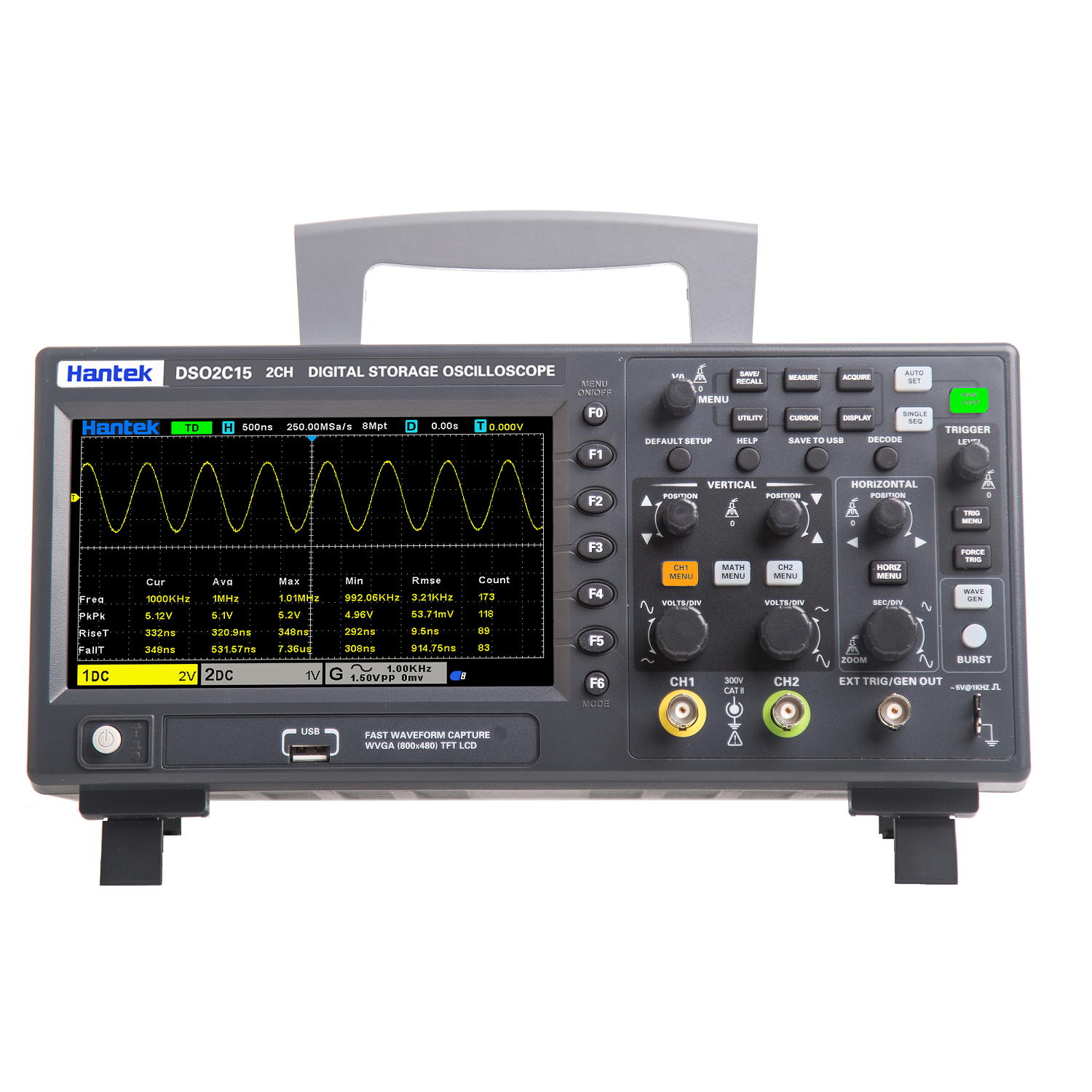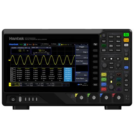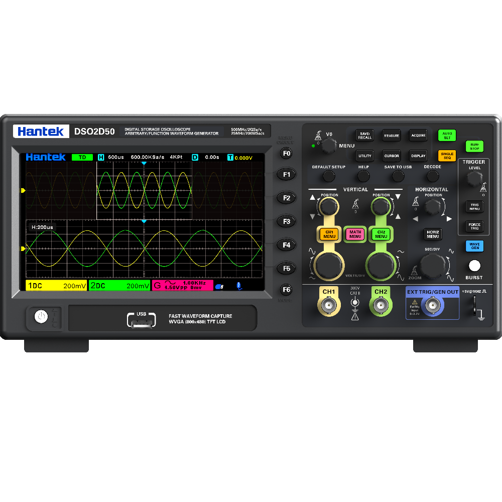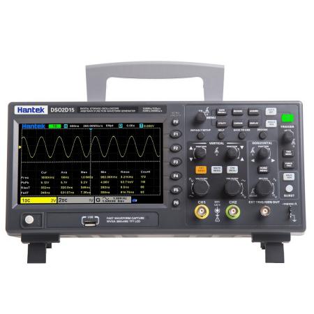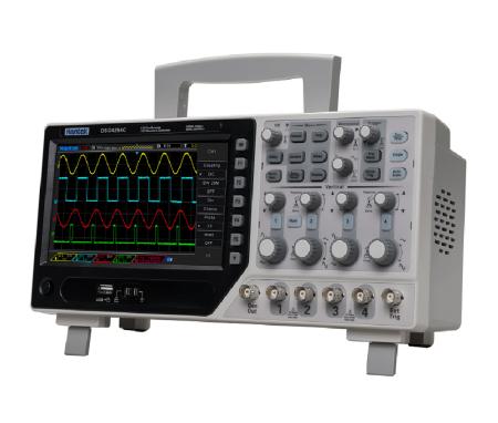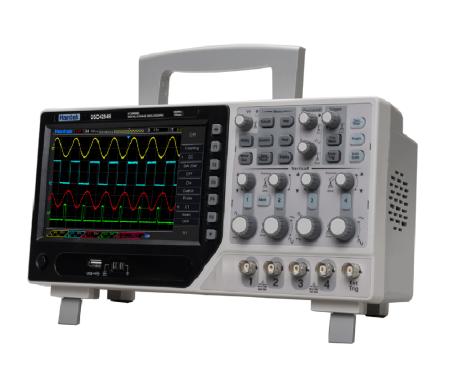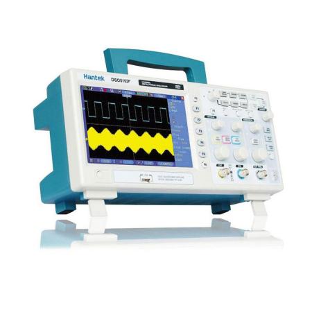
DSO2000 Series
![]() Feature:
Feature:
1) 2 channels which are respectively controlled by independent knobs
2) 100 MHZ and 150MHZ analog channel bandwidth
3) Sampling rate up to 1 GSa/s
4) 8M memory depth
5) Vertical range 2mV/div ~ 10V/div
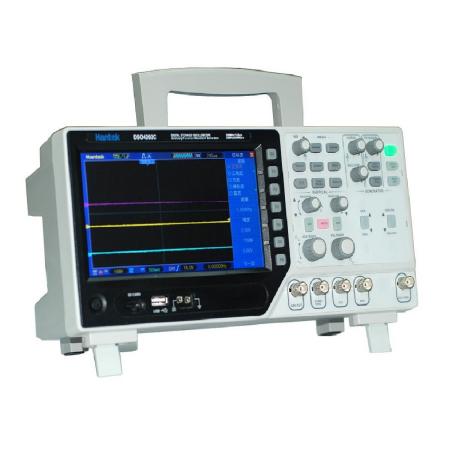
6) Built-in 1 CH 25MHz waveform generator (DSO2D10, DSO2D15)
7) Vertical resolution: 8bit
8) Trigger: Edge, Pulse, Video, Slope, Overtime, Window, Pattern, Interval, Under Amp, UART, LIN, CAN, SPI, IIC
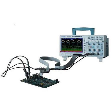
9) BUS decode and protocol analysis: RS232/UART, I2C, SPI, CAN, LIN
10) Can save multiple data formats, such as settings, waveforms, reference waveforms, CSV, pictures
11) A 3-digit digital voltage meter and a 6-digit hardware frequency indicator
12) 32 kinds of auto measurements with statistics, real-time statistics of maximum, minimum, standard deviation and etc.
13) 2 sets of digital voltmeters
14) Support threshold testing, free measurements within the screen
15) Abundant SCPI remote command control
16) USB Host/Device.
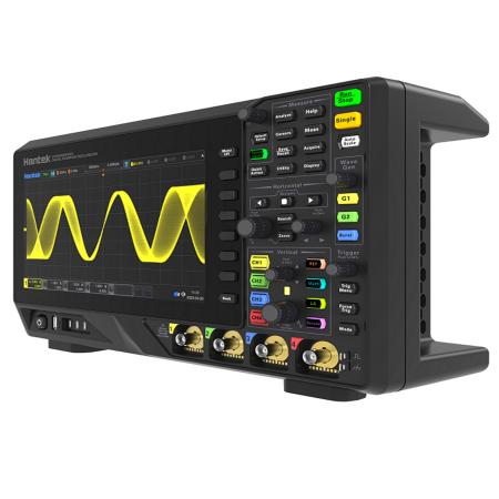
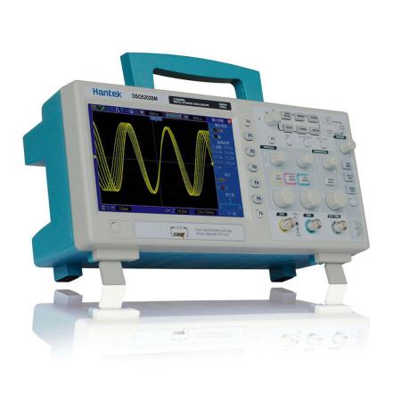
![]() Model
Model

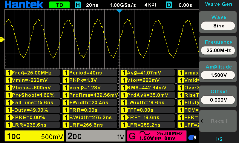
![]() 1CH 25MHz waveform generator, support arbitrary waveform burst output, support modulation waveform output
1CH 25MHz waveform generator, support arbitrary waveform burst output, support modulation waveform output
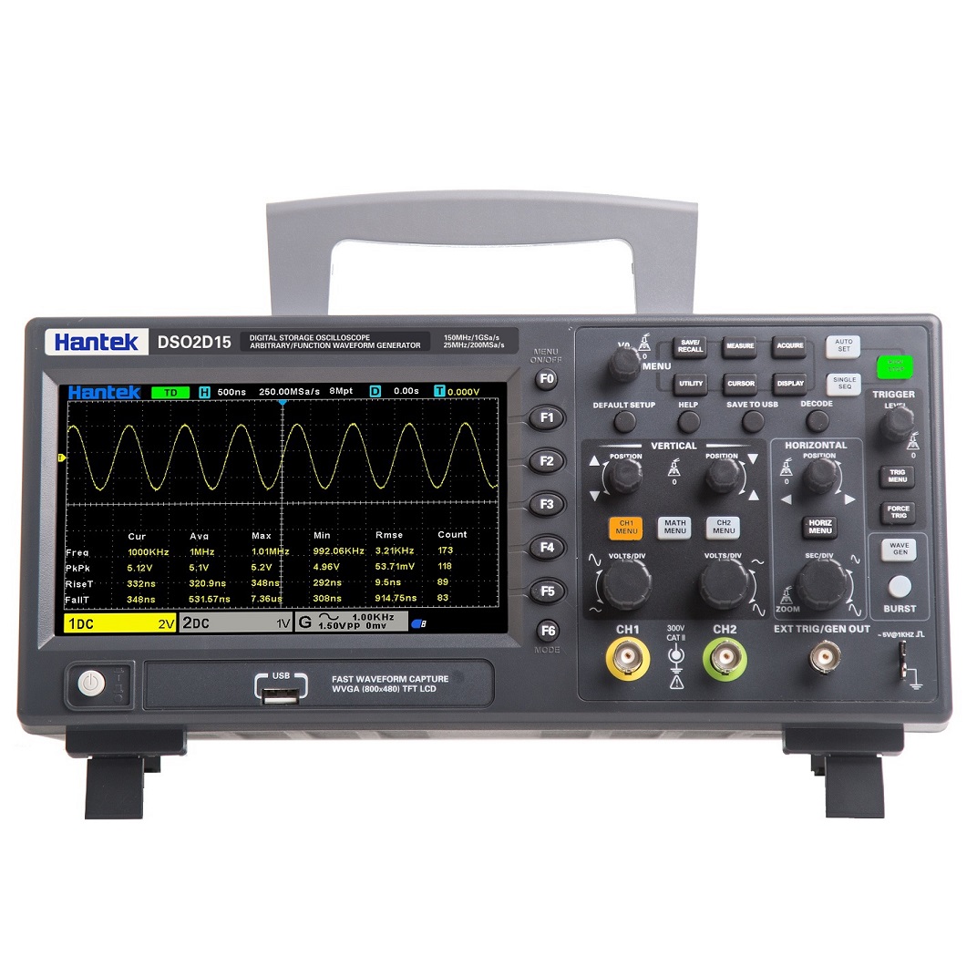
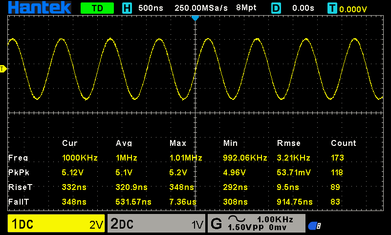
![]() 32 kinds of auto measurements with statistics
32 kinds of auto measurements with statistics
![]() Can save 9 sets of reference waveforms, CSV waveforms and settings. The USB one-click screenshot function.
Can save 9 sets of reference waveforms, CSV waveforms and settings. The USB one-click screenshot function.

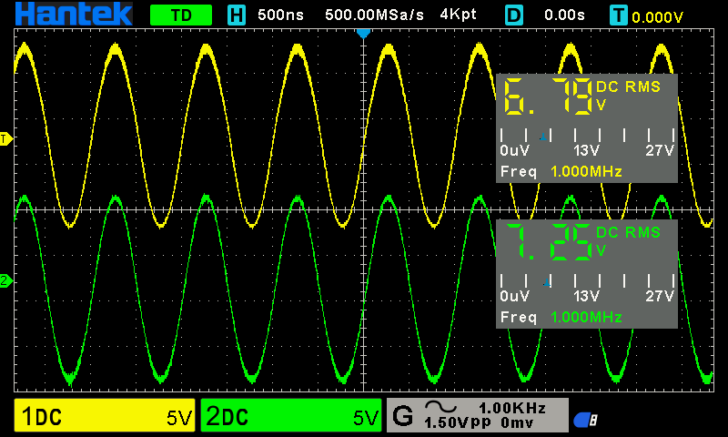
![]() 2 sets of DVM, 3-digit digital voltage meter and 6-digit hardware frequency indicator functions
2 sets of DVM, 3-digit digital voltage meter and 6-digit hardware frequency indicator functions
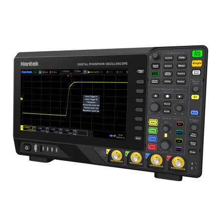
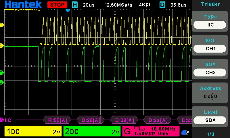
![]() Serial bus trigger and decode, with the protocol monitoring function
Serial bus trigger and decode, with the protocol monitoring function
![]() 8M memory depth, reducing waveform distortion and restore real waveforms
8M memory depth, reducing waveform distortion and restore real waveforms
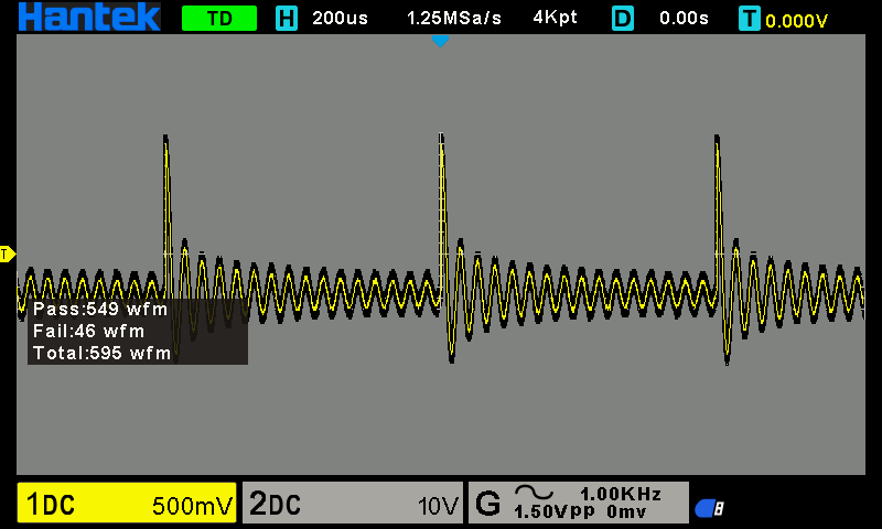
![]() PASS/FAIL
PASS/FAIL
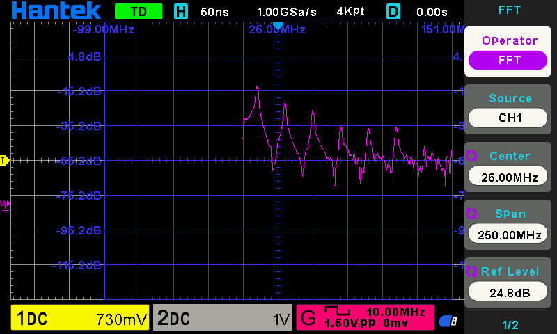
![]() Mathematical operation and FFT
Mathematical operation and FFT
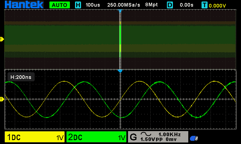
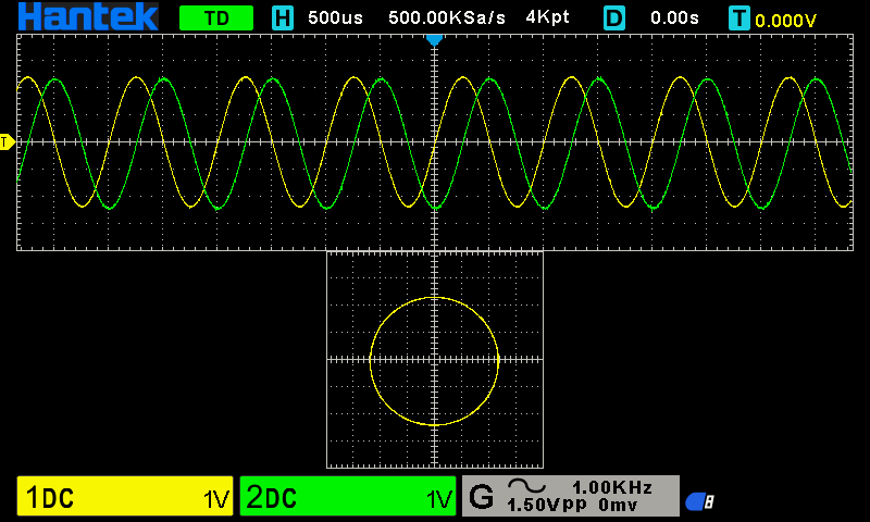
![]() X-Y format and display in dual windows
X-Y format and display in dual windows
![]() Parameters
Parameters
Model
DSO2D15
DSO2D10
DSO2C15
DSO2C10
Bandwidth
150MHz
100MHz
150MHz
100MHz
Oscilloscope channels
2CH
2CH
2CH
2CH
Waveform generator
1CH
1CH
-
-
Oscilloscope
Sample rate
1GSa/s
(single channel) 500MSa/s (two channels)
Acquisition
Normal
Sample
data
Peak-to-peak value
Display
high frequency and random burr
Average
Average
waveform, times: 4, 8, 16, 32, 64, 128
High resolution
Up to
12bit
Input
Input coupling
DC,
AC, GND
Input impedance
1MΩ±2%
‖13pF±3pF
Probe attenuation factor
1X,
10X, 100X, 1000X
Voltage rating
300V
CAT II
Maximum input voltage
300VRMS
(10X)
Horizontal
Waveform interpolation
(sin
x)/x
Maximum record length
Single
channel maximum 8M
Two channels maximum 4M
Horizontal scale range
2ns/div~100s/div
1, 2, 5 step by step
Time base mode
Y-T,
X-Y, Roll
Zero offset
±0.5
div×minimum time base gear
Sample Rate and Delay Time Accuracy
±25ppm
Delta Time Measurement Accuracy (Full
Bandwidth)Sample Rate and Delay Time Accuracy
single-shot,
Normal mode ±(1
sample interval+100ppm×reading+0.6ns)
>16 times
averages ±(1
sample interval+100ppm×reading+0.4ns)
Sample interval=sec/div÷200
Sample Rate and Delay Time Accuracy
±50ppm(at
any interval greater than 1ms)
Vertical
Model
DSO2D15
DSO2D10
DSO2C15
DSO2C10
Bandwidth
150MHz
100MHz
150MHz
100MHz
Rising time in BNC position (typical)
2.4ns
3.5ns
2.4ns
3.5ns
Vertical resolution
8
bits resolution, each channel samples simultaneously
Vertical sensitivity
2mV/div
to 10V/div
Offset range
≥ 200mV/div, ±1V;
<200mV/div
±50V
Mathematical operation
+, -,
×, ÷, FFT
FFT
Window:
Rectangle, Hanning, Hamming, Blackman, Bartlett, Flattop
Bandwidth Limit
20MHz
Bass response(-3db)
In
BNC position ≤ 10Hz
Vertical gain accuracy
In
''normal'' or ''average'' acquisition mode, the accuracy of
10V/div to 10mV/div is ±3%;
In ''normal'' or ''average'' acquisition mode, the accuracy
of 5mV/div to 2mV/div is ±4%
Note:
Bandwidth reduced to 6MHz when using a 1X probe
Trigger
Trigger type
Edge, Pulse
width, Video, Slope, Overtime, Window, Pattern, Interval,
Under Amp, UART, LIN, CAN, SPI, IIC
Trigger level range
±5
divisions from the center of the screen
Trigger mode
Auto,
Normal, single
Level
CH1~CH2
±4
divisions from the center of the screen
EXT(Only With AWG Model)
0~3.3V
Holdoff range
8ns~10s
Trigger level accuracy
CH1~CH2
0.2
div×volts/div within ±4 divisions from the center of the screen
EXT(Only With AWG Model)
±(Set
value× 6%+40mV)
Edge trigger
Slope
Rising
edge, falling edge, rising or falling edge
Signal source
CH1, CH2, EXT(Only With AWG Model)
Pulse width trigger
Polarity
Positive
polarity, negative polarity
Condition(When)
<,
>, !=, =
Signal source
CH1~CH2,
Pulse width range
8ns ~
10s
Accuracy
8ns
Video trigger
Signal
standard
NTSC,
PAL
Signal source
CH1~CH2
Synchronization
Scanning
line, line number, odd field, even field, all field
Slope trigger
Slope
rising,
falling
Condition(When)
<,
>, !=, =
Signal source
CH1 ~
CH2
Time range
8ns ~
10s
Accuracy
8ns
Overtime trigger
Signal
source
CH1~CH2,
Polarity
Positive
polarity, negative polarity
Time range
8ns ~
10s
Accuracy
8ns
Window trigger
Signal
source
CH1~CH2
Pattern trigger
Pattern
0:
low level; 1: high level; X: ignore
Level(signal source)
CH1~CH2
Interval trigger
Slope
rising,
falling
Condition(When)
<,
>, !=, =
Signal source
CH1~CH2
Time range
8ns ~
10s
Accuracy
8ns
Under Amp trigger
Polarity
Positive
polarity, negative polarity
Condition(When)
<,
>, !=, =
Signal source
CH1~CH2
Time range
8ns ~
10s
Accuracy
8ns
UART trigger
Condition(When)
Start,
Stop, data, Parity ERR, COM ERR
Signal source(RX/TX)
CH1~CH2
Data format
Hex
(hexadecimal)
Data length
1
byte
Data bit width
5
bit, 6 bit, 7 bit, 8 bit
Odd-even check
none,
odd, even
Idle level
high,
low
Baud rate (optional)
110/300/600/1200/2400/4800/9600/14400/19200/38400/57600/115200/230400/380400/460400
bit/s
Baud rate(user-defined)
300bit/s~334000bit/s
LIN trigger
Condition(When)
Interval
field, synchronization field, ID field, synchronization error, identifier, ID
and data
Signal source
CH1~CH2
Data format
Hex
(hexadecimal)
Baud rate (optional)
110/300/600/1200/2400/4800/9600/14400/19200/38400/57600/115200/230400/380400/460400
bit/s
Baud rate(user-defined)
300bit/s~334000bit/s
CAN trigger
Condition(When)
Start
bit, remote frame ID, data frame ID, frame ID, data frame data, error frame,
all errors, ACK Error, overload frame
Signal source
CH1~CH2
Data format
Hex
(hexadecimal)
Baud rate (optional)
10000,
20000, 33300, 500000, 62500, 83300, 100000, 125000, 250000, 500000, 800000,
1000000
Baud rate(user-defined)
5kbit/s~1Mbit/s
SPI trigger
Signal
source
CH1~CH2
Data format
Hex (hexadecimal)
Data bit width
4, 8,
16, 24, 32
IIC trigger
Signal
source (SDA/SCL)
CH1~CH2
Data format
Hex (hexadecimal)
Data index
0~7
When(condition)
Start
bit, stop bit, No Ack, address, restart, address and data
Measurement
Cursor
Voltage
difference between cursors △V
Time difference between cursors △T
Reciprocal of △T, in Hertz (1/△T)
Auto measurement
frequency,
period, mean, peak-to-peak, RMS, minimum, mixmum, rising time, falling time,
+ width, - width, base, top, middle, amplitude, overshoot, preshoot, rising
edge phase difference, falling edge phase difference, + duty, - duty, period
mean, PRMS, FOVshoot, ROVshoot, BWIDTH, FRF, FFR, LRR, LRF, LFR, LFF
DVM
Data
source
CH1,
CH2
Measurement type
DC
RMS
AC RMS
DC
Frequency meter
hardware
6 bits frequency meter
Arbitrary
waveform generator
Channel
1
Sample rate
200MSa/s
Vertical resolution
12
bits
Maximum frequency
25
MHz
Standard waveforms
sine,
square, ramp,Exp, noise, DC
Arbitrary waveform
Arb1,
Arb2, Arb3, Arb4
Sin
Frequency
range
0.1Hz~25MHz
Square/pulse
Frequency
range
0.1Hz~10MHz
Triangular wave
Frequency
range
0.1Hz~1MHz
Sampling wave
Frequency
range
0.1Hz~1MHz
Index
Frequency
range
0.1Hz~5MHz
Noise
Arb1
Frequency
range
0.1
Hz to 10 MHz
Arb2
Frequency
range
0.1
Hz to 10 MHz
Arb3
Frequency
range
0.1
Hz to 10 MHz
Arb4
Frequency
range
0.1
Hz to 10 MHz
Waveform length
4KSa
Frequency
Accuracy
100
ppm (<10 kHz) 50 ppm (>10 kHz)
Resolution
0.1
Hz or 4 bits,take the greater one
Amplitude
Output
range
10mV~7Vp-p
(high impedance)
5mV~3.5Vp-p (50Ω)
DC offset
Range
±3.5
V, high impedance
±1.75 V, 50 Ω
Resolution
100
μV or 3 bits, take the greater one
Accuracy
2% (1
kHz)
Output impedance
50 Ω
General
specifications
Display
Display
type
7'' diagonal TFT liquid
crystal
Display resolution
800
(horizontal)*480 (vertical) pixels
Display colour
16
million colours (24 bits true colour)
Persistence time
minimum, 1
s, 5 s, 10 s, 30 s, infinite
Display type
dot,
vector
Display brightness
adjustable
Grid type
adjustable
Grid brightness
adjustable
Interface
Standard
interface
USB
Host,USB Device
General specifications
Probe
compensator output
Output voltage, typical
about
2Vpp input ≥1MΩ load
Frequency, typical
1kHz
Power supply
100-120VACRMS(±10%), 45Hzto 440Hz,
CATⅡ
120-240VACRMS(±10%), 45Hz to 66Hz, CATⅡ
Power consumption
<30W
Fuse
T,
3.15A, 250V, 5x20mm
Operating temperature
0~50
°C (32~122 °F)
Storage temperature
-40~+71
°C (-40~159.8 °F)
Humidity
≤+104℉(≤+40°C):
≤90% relative humidity
106℉~122℉ (+41°C ~50°C): ≤60% relative humidity
Altitude
Operating
and nonoperating
3,
000m (10, 000 feet)
Mechanical shock
Random
vibration
0.31
g RMS from
50Hz to 500Hz,
10 minutes on each axis
Nonoperating
2.46g RMS from 5Hz
to 500Hz,
10 minutes on each axis
Operating
50g,
11ms, half-sine wave
Mechanical
Size
318 x
110 x 150mm (length x width x height)
Weight
1900g
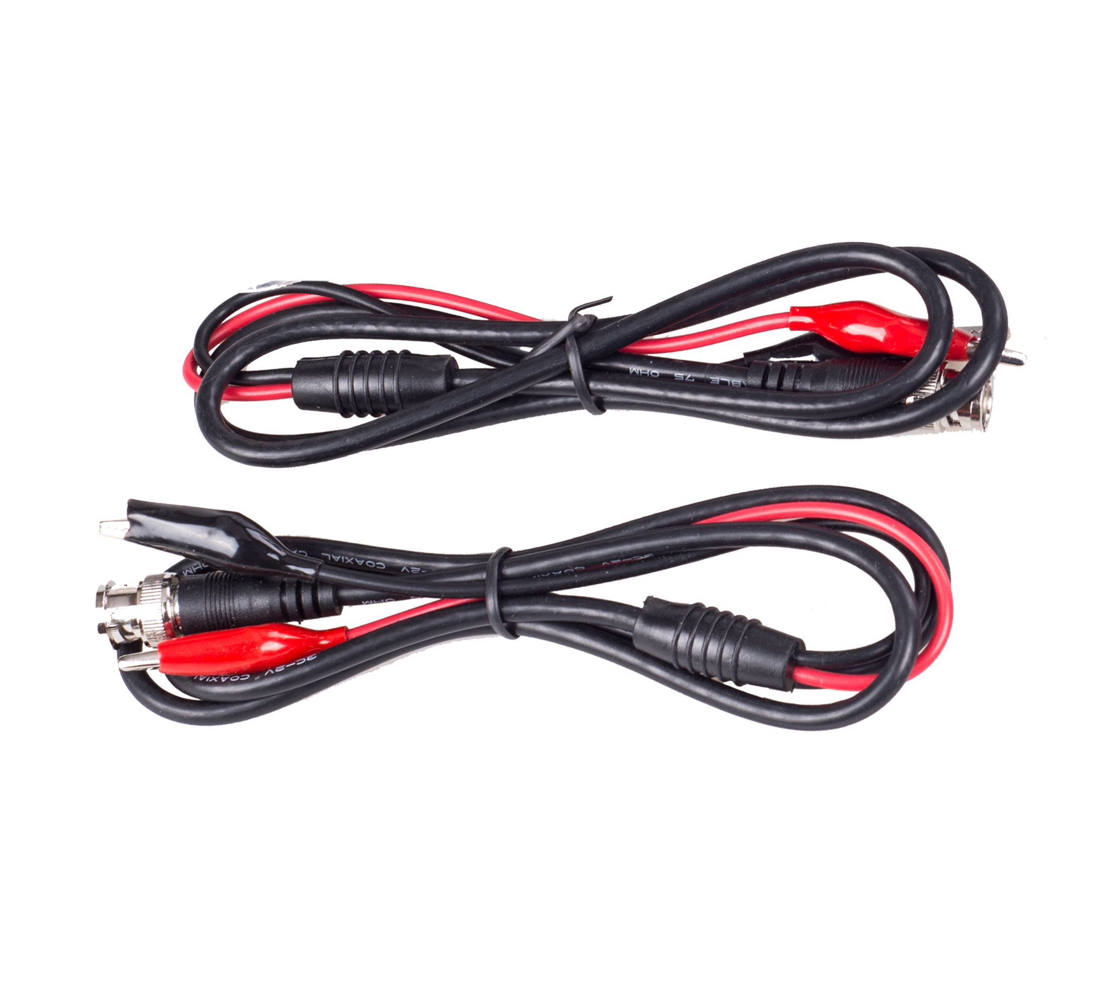
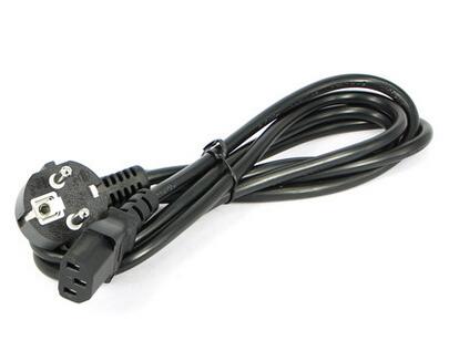
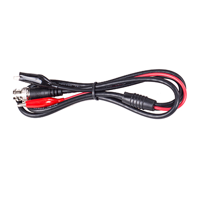
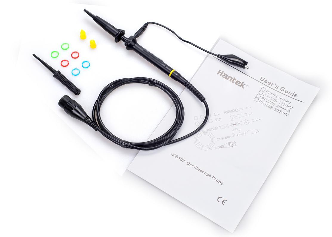
![]() Accessories
Accessories
DSO2D15, DSO2D10:
|
|
|
|
|
 |
 |
DSO2C10, DSO2C15:
|
|
|
|
|
|
|
|
|